3 Floor Elevator Plc Ladder Logic Pdf
Https Www Krishisanskriti Org Vol Image 05aug201707084903 20 20 20 20 20 20 20 20 20 20sanjukta 20behera 20 20 20 20 20 20 20 20 20 20 20 20 20 2040 43 Pdf

Plc Ladder Logic Symbols Motor Control Circuits Plc Programming Ladder Logic Electrical Circuit Diagram
Https Www Ijser Org Researchpaper Implementation Of A Four Floor Programmable Logic Controlled Elevator System Pdf

Asi Free Full Text Development Of Lift Control System Algorithm And P M E Analysis In The Workplace Html

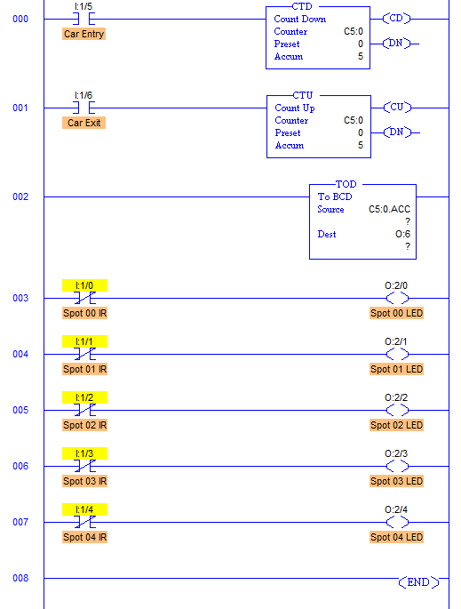
Plc Program For Entry Exit Control Of Car Parking Instrumentation Tools Car Parking Ladder Logic Tutorial
Http Www Internationaljournalssrg Org Ijeee 2019 Volume6 Issue2 Ijeee V6i2p101 Pdf

Latching rung to operate the system through master start and stop pb.
3 floor elevator plc ladder logic pdf.

Plc Logic Gate Write A Plc Ladder Logic For And Gate Or Gate Not Gate And Xor Agte Explore Plc Tutorials Ladder Logic Programmable Logic Controllers Logic
Https Www Ijireeice Com Upload 2017 April 17 Ijireeice 2026 Pdf
Plc Elevator Project Youtube
Plc Program For A Car Parking System Sanfoundry
Source : pinterest.com
